PC Recorder R7K4GUS Series
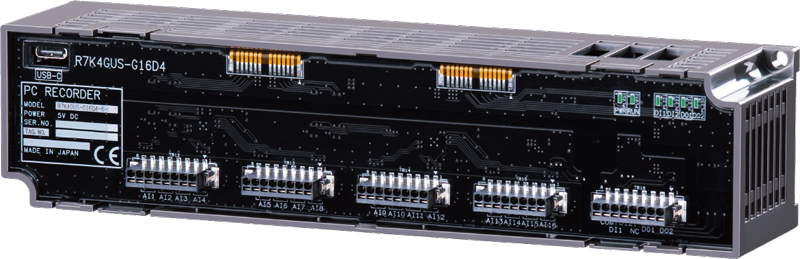
Model: R7K4GUS-G16D4
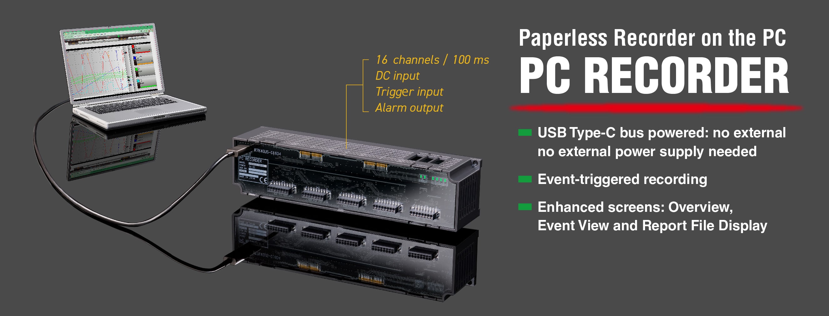
Paperless Recorder on the PC
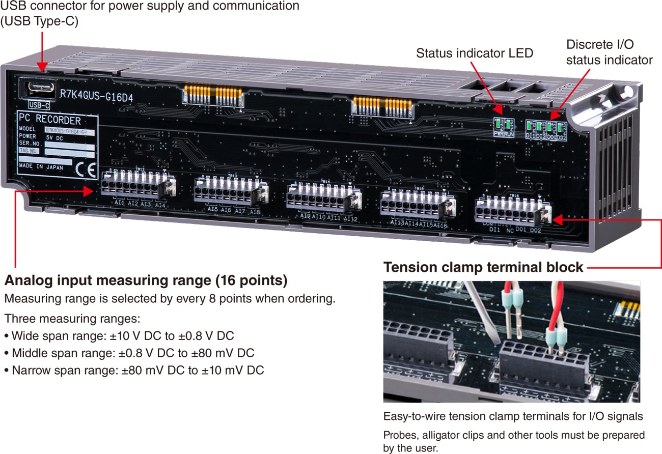
- USB Type-C bus powered: no external power supply needed
- Event-triggered recording
- Enhanced screens: Overview, Event View and Report File Display

No External Power Supply Needed!
Paperless Recorder that is as easy to use as a digital multimeter
No External Power Supply Needed!
Paperless Recorder that is as easy to use as a digital multimeter
What You Need to Start Data Recording
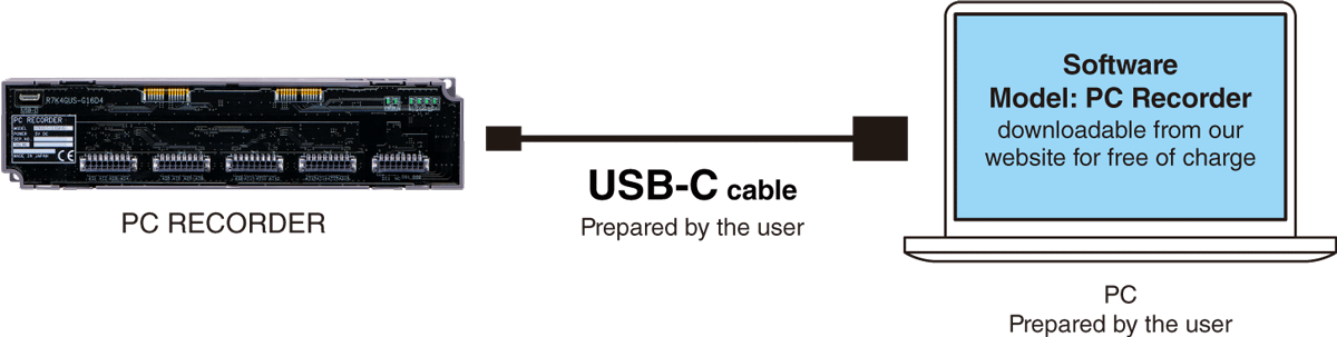
Operating system: Windows 11
Browser: Chrome, Edge, Firefox
Language: English / Japanese
Application Examples
-

Type testing (e.g. thermostatic chamber)
-

Equipment failure analysis
-

Laboratory testing on moving vehicles
Enhanced Screens Beside the Trend Graph
The operability of PC Recorder follows that of the existing products of Web Data Logger and Tablet Recorder which have already been used and familiar to many users.
-
GRAPH
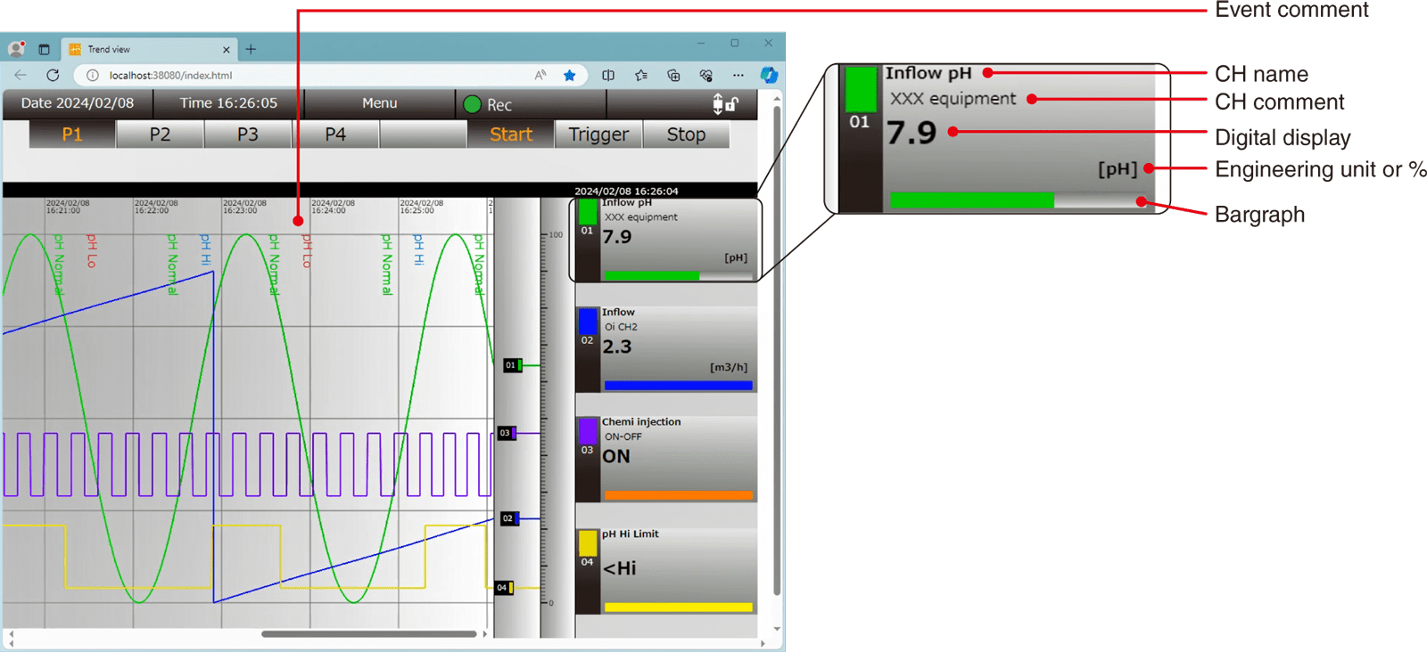
Trend View
-
There are four trend graph pages, each of which contains 4 pens (16 pens in total).
Each pen is assigned to any channel of all I/Os (Ai / Di / Oi / Do).
Zone name, zone color, event comment, alarm output, delay timer, trigger recording and reset function value, can be specified to each analog input channel (Ai) and operation input channel (Oi).
Trend Display Functions
| Number of pens | 16 (4 pens per page) |
|---|---|
| I/O channels assigned to pens |
Ai, Di, Oi, Do (all channels) |
| Graph scale | 0% and 100% positions specified by engineering unit values |
| Data format | .TRD file format |
| Data contents | Trend, event history, comment history |
| Data size | Max. 50000 samples per file x 16 pens |
| Auto-start | Recording can start automatically when the program is started. Specify either Stop / Normal / Trigger. |
| Storing interval | 100, 500 ms, 1, 2, 5, 10 s, 1, 2, 5, 10, 30 min, 1 hour |
-
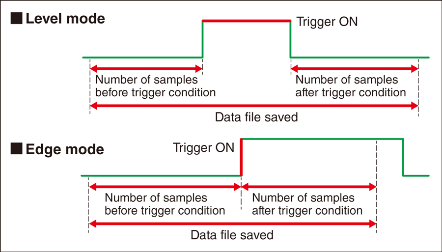
Trigger Recording
User can preset specific trigger conditions to certain analog/digital/operation channels, and choose how many data samples before and after an event condition is triggered, must be recorded.
It is an effective way to save only the necessary data for failure monitoring and analysis.
Two operation modes are available: “Level” mode and “Edge” mode. -
-
ALL CHANNELS
Overview
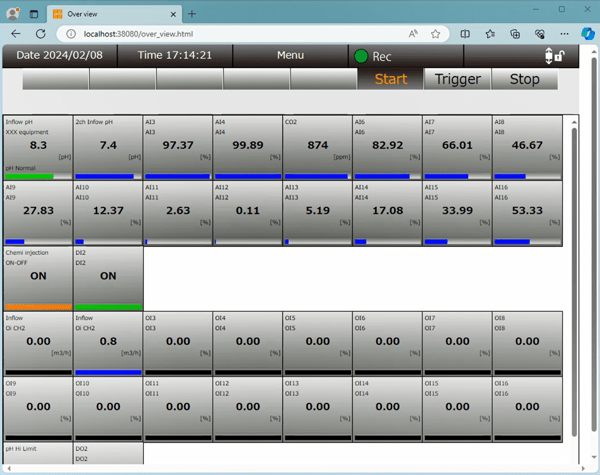
All channels are updated and displayed on the overview screen. For analog input channels, engineering unit values and percent values are toggled by clicking over the display.
-
LATEST EVENTS
Event View
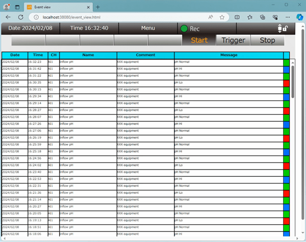
The latest 500 events, triggers, alarms are listed among the analog and operation input signal channels.
-
REPORT FORMS
Report File
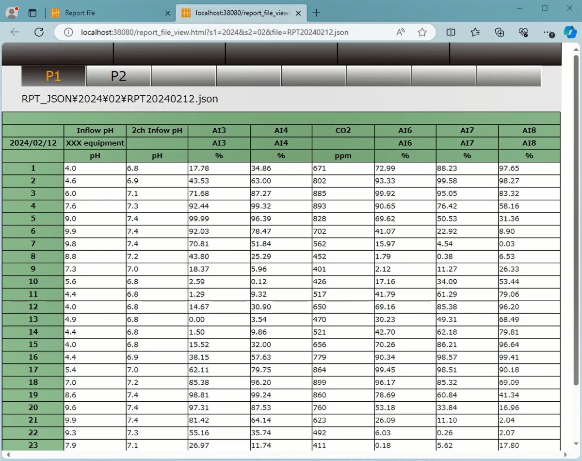
Report file data is generated every hour on the hour (1H data). Sampling method can be selected from momentary / average / maximum / minimum values.