Digital Panel Meters
47L Series (LED display type)
1/8 DIN Size, 4 to 4 1/2 Digit LED Display Type
- 96 x 48 mm
- LED color selectable: Red, Orange, Green, Bluegreen, Blue, White
- Field-selectable input range
- 100-240 V AC or 24 V DC powered
- Options: alarm, transmitter output
- IP66 front panel
- Separable terminal block


Depending on the model.
-
Form Factor
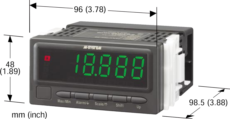
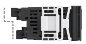
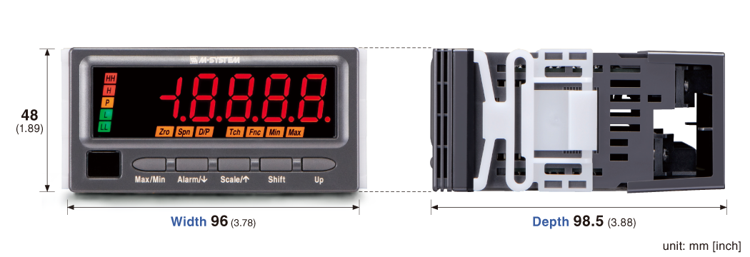
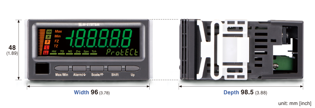
Figure 1. 47 Series External Appearance and Dimensions (47LV)Figure 1 illustrates the external appearance and dimensions of a typical 47 Series meter.
The 47 series retains our noted performance and functionality in a new stylish design.
With a depth of 98.5 mm (3.88"), the 47 Series is shorter than previous 46 Series models, which range from 100 to 104 mm in depth. It also adds to the low-profile control boards and devices we currently offer, benefiting users with improved space efficiency.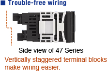
Figure 2. Vertically Staggered Terminal BlocksAdditionally, a number of design refinements facilitate easy wiring. For example, vertically staggered terminal blocks on the rear of the case help keep connected cables from becoming tangled (see Figure 2).
-
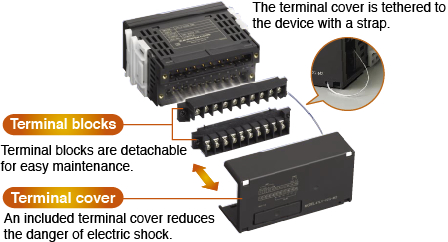 Figure 3. 47 Series Design
 Thanks to a 2-piece detachable terminal block design (allowing the terminal blocks to be removed from the device), there is no need to disconnect numerous cables from the terminal blocks when removing the device from the panel for inspection or maintenance purposes. An included terminal block cover reduces the danger of electric shock so that personnel can work safely inside panels (see Figure 3).
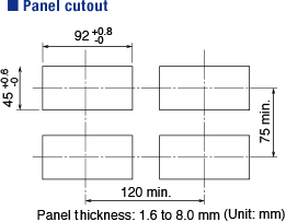
Figure 4. 47 Series Mounting RequirementsThe 47 Series is compatible with standard 48 x 96 digital panel meter cutouts (see Figure 4), and digital panel meters of this size can be easily replaced by a 47 Series unit.
-
Front Panel Provides IP66-level Protection
The front panels of 47 Series meters provide IP66-level protection so that they can be used with peace of mind near water and in environments where they might be exposed to dust or splashing water.
When mounting a 47 Series meter in a panel, the included clip can be used to enable one-touch attachment of the device without tools after it is inserted into the panel cutout.Bright, Clear, and Colorful Displays
47 Series LED meters use internal LEDs to display useful information to the user. High-brightness LEDs are used to create a display that is bright, clear, and sharp.
In addition, the display brightness can easily be set by the user to any of 5 levels by means of a button on the front of the device to match the environment in which the meter is being used.
Users may specify a variety of display colors in addition to standard red and green configurations, including orange, blue-green, blue, and white, making it easy to customize LED display type 47 Series meters for use in unique applications.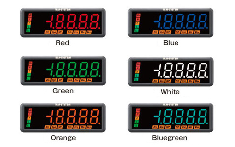
-
Operability
We set out to build intuitive operability into the 47 Series.
The goal of the design process was that users could easily understand its basic operation after reading through the instruction manual and operating the meter immediately.
The configuration of 47 Series meters is aided by easy-to-understand displays of alphabetical and numerical settings, function configuration status, and alarm result status on the main display.
Operation has been simplified by allocating the Scale and Alarm buttons to the first scaling configuration function (excluding the 47LT and 47LR) and alarm configuration function used, respectively (see Figure 5). A device-protect function or lockout prevents unintended configuration changes.
We have kept operation from becoming too complex by carefully selecting and including only necessary functionality, including a moving average to suppress the display flickering and a Max./Min. display value.External View (Model: 47LV)
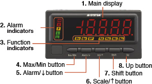
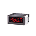
Figure 5. 47 Series Front Panel (47LV with red display)No. Component Functions (1) Main display Indicates present values, setting values and status of the unit. (2) Alarm indicators Indicate alarm status of the input signal. (3) Function indicators Indicate the status in each setting mode. (4) Max/Min button Used to switch the main display to show the present values, maximum values or minimum values etc. (5) Alarm /↓button Used to confirm alarm setting value and to move on to the alarm and other setting modes; or to shift through setting items in each setting mode. (6) Scale /↑button Used to move on to the scaling and other setting modes; or to shift through setting items in each setting mode. (7) Shift button Used to move on to the setting standby status of each setting mode and shift through display digits in each setting mode. (8) Up button Used to change setting values, to execute/cancel Forced Zero or to select setting values. Note: Refer to the operating manual for details on each function.
Digital Panel Meters
47D Series (LCD display type)
1/8 DIN Size, 5 1/2 Digit LCD Display Type
Depending on the model.
- 96 x 48 mm
- Red or Green LCD selectable (negative type LCD with LED backlight)
- Field-selectable input range
- Excitation supply +12 V, +24 V
- 100-240 V AC or 24 V DC powered
- Options: alarm, transmitter output, BCD, RS-485 / Modbus RTU, event trigger input
- IP66 front panel
- Separable terminal block
-
The easy-to-use 47 series retains our noted performance and functionality in a new stylish design.
The 47 Series lets you choose from LED display type models and LCD display type models. Both display types offer the following features:· Vertically staggered terminal blocks for easy wiring.
· Detachable two-piece terminal blocks for convenient maintenance.
· Standard 48 x 96 panel cutout size allowing 47 Series models to be used as replacements for other meters.
· IP66 protection front panel.
· One-touch panel attachment — No need for tools!
LCD display type models augment the above features with an additional range of functionality.
Table 1 Outlines the LCD display type models (input types) of the 47 Series.Table 1
Model Function 47DV DC input 47DT Thermocouple input 47DR RTD input 47DM Potentiometer input 47DAC AC input Display
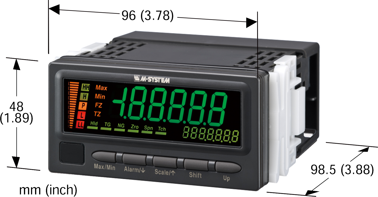
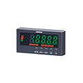
Figure 1. 47 Series External Appearance and Dimensions (LCD Display Type)Figure 1 Illustrates the external appearance of 47 Series LCD display type models.
-
Figure 2 provides a diagram of the front panel.
The 47D models features an LCD display, which enables it to provide more detailed information without increasing power consumption compared to LED type models. Taking advantage of this feature, this model offers a bar graph that covers the full display range able to be seen at a single glance. They use a high-brightness LED backlight and support switching of display colors, allowing alarms to be indicated by changes of the display color.
The main display readout switches from green to red when the unit enters an alarm state (it can also be configured to change from red to green). This feature is designed to inform the state of the device from a reasonable distance based on changes in the display color.Figure 2. 47 Series Front Panel (LCD Display Type, 47DV)
No. Component Functions (1) Main display Indicates present values, setting values and status of the unit. (2) Sub display Indicates the present setting mode. (3) Status indicators Indicate Max/Min display mode, Forced zero mode and Tare adjustment mode. (4) Alarm indicators Indicate alarm status of the input signal. (5) Bargraph Indicates present signal level against the scaled range. (6) Function indicators Indicate the device status. (7) Infrared interface Used for the infrared communication. (8) Max/Min button Used to switch the main display to show present values, maximum values or minimum values etc. (9) Alarm /↓button Used to confirm alarm setpoints and to move on to the alarm and other setting modes; or to shift through setting items in each setting mode. (10) Scale /↑button Used to move on to the scaling and other setting modes; or to shift through setting items in each setting mode. (11) Shift button Used to move on to the setting standby status and shift through display digits in each setting item. (12) Up button Used to change and apply setting values; or to execute/cancel Forced Zero and tare adjustment. Note: Refer to the operating manual for details on each function.
-
Operability
The 47D models are designed to fulfill the seemingly contradictory demands of intuitive operation and extensive functionality. The goal of the design process was to allow users to understand basic operations and use after reading through the instruction manual one time.
The features most frequently used initially after powering on the meter are likely to be the alarm setting function and the scaling function. Each of these functions have been assigned to a single button located on the front panel and labeled with the name of the function to allow instant access to setting mode.
There is also a security function to prevent unintended setting changes. Models take advantage of the detailed display made possible by the use of an (11) Shift buttonLCD as described above to offer the maximum possible level of functionality while delivering intuitive operation. Table 2 lists a selection of representative functions.Table 2. Representative 47 Series LCD Display Type Functions
No. Function name Description 1 Max/min value display Indicates maximum and minimum values. 2 Forced zero Shift the present display value to zero and continues to measure in reference to this point. 3 Tare adjustment Sets another zero point relative to the forced zero point. 4 Alarm output pattern Allows switching between normal and zone output. 5 On/off delay Delays operation after an alarm turns on or off. 6 Short output Holds output for a fixed interval after an alarm turns on. 7 Bank function Allows configuration of eight alarm value patterns. 8 Simple average / moving average Averages and displays measured values. 9 Zero limit Allows values less than or equal to a set value to be displayed as zero. 10 Display color selection Allows selection of the display color switching pattern. 11 Change P output Assigns pass output to the desired alarm output. 12 Alarm output latch Output or both output and reading are held in an alarm state. 13 Standby sequence Allows standby operation from the time that the meter is turned on until it first enters the pass state. 14 Scaling error alarm operation Allows selection of whether to generate alarm output when outside the measurement range. 15 Minimum digit step Disables display of values less than or equal to a set value. 16 Compare to previous average
(high-pass filter)Displays only fast-moving changes. 17 Brightness/contrast adjustmens Allows the display conditions to be changed. * Refer to each model's instruction manual for details on operation.
-
Infrared Communications
LCD display type 47 Series models support an infrared communication adaptor (Model: COP-IRU). The adaptor can be used to configure the device from a computer without requiring either a cable connection or access to the unit’s front panel. (see Figure 3).
PC configurator software (Model: 47DCFG) is also available for use with the adaptor. The software can be downloaded from our website.
Used in combination with the PC configurator software, this infrared communication adaptor eliminates the need to check various settings while repeatedly pressing the buttons on the unit’s front panel. Instead, you can set and check settings on a large computer screen.
Additionally, the ability to edit, save, and load equipment parameters and manage parameter files eliminates the fuss when using control panels equipped with multiple 47 Series digital panel meters as long as the meters use the same settings. You only need to load the parameter file and write (send) it to each unit.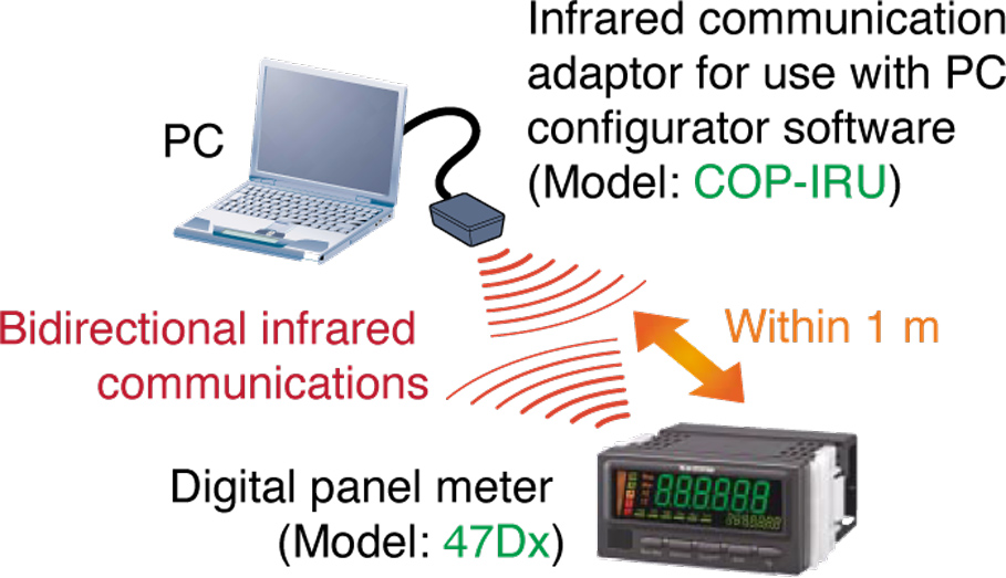
Figure 3. Configuration with the Infrared Communication AdaptorDC Output and Modbus Communications
DC output has five calibration types available (4 to 20 mA, 0 to 20 mA, 0 to 5 V, ±5 V, and ±10 V) using the buttons on the unit’s front panel to configure without changing terminal block connections. The withstand voltage between inputs and DC outputs is AC 2,000 V for 1 minute. Furthermore, the 47 Series meters offer a loop test function for which output can be set to the desired value, a convenient feature when getting a system up and running.
47 Series also offer RS-485 Modbus communications, allowing them to send measured values or setting values to an upstream computer or other device making it easy to implement data gathering and analysis from multiple meters. Additionally, the full range of meter functionality is supported, including the changing of alarm values and display colors. Figure 4 illustrates an example system architecture.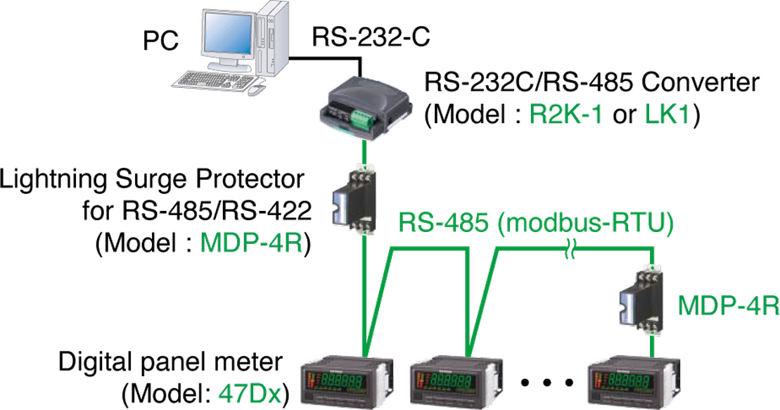
Figure 4. System Configuration Example Using Modbus Communications -
Excitation Supply
The 47 Series includes an excitation supply. Users can choose from two-wire transmitter excitation (+24 V) and sensor excitation (+12 V) at the time of purchase (except for 47DAC).
With two-wire transmitter excitation models, you can monitor and display 20 mA transmitter output just by connecting a DC input type meter (47DV) to a two-wire transmitter with two wires. Smart transmitters (e.g., with HART) are also supported.
Additionally, units with either type of excitation supply now display an error on the front panel when an unexpected shortcircuit occurs. Naturally, a shortcircuit protection function is included. -
Thanks to a 2-piece detachable terminal block design (allowing the terminal blocks to be removed from the device), there is no need to disconnect numerous cables from the terminal blocks when removing the device from the panel for inspection or maintenance purposes.
An included terminal block cover reduces the danger of electric shock so that personnel can work safely inside panels.
-
Additionally, a number of design refinements facilitate easy wiring.
For example, vertically staggered terminal blocks on the rear of the case help keep connected cables from becoming tangled