The old company name and logo may still be indicated on products, printed materials or web site published before its change.
Those shall be read as the new ones.
| TECHNICAL INFORMATION |
| Effective Use of the Math Function Module (2) |
| In the last issue, gain and bias calculations
were explained for the adder-subtractor module frequently used in process instrumentation.
In this issue, usage of the math function module as it applies to multiplication
and division will be discussed. The multiplier-divider is widely used for temperature
and pressure compensation in flow measurement.
|
| Multiplier-divider |
 The
multiplier-divider is commonly used for temperature and pressure compensation
in the volumetric method of gas flow measurement. Liquid volume variations with
temperature and pressure are very little. However, gas volume changes due to the
effect of temperature and pressure variations. The
multiplier-divider is commonly used for temperature and pressure compensation
in the volumetric method of gas flow measurement. Liquid volume variations with
temperature and pressure are very little. However, gas volume changes due to the
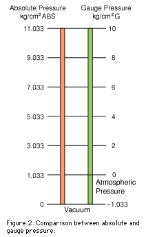
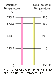
effect of temperature and pressure variations.The characteristics of this phenomenon are expressed in Boyle’s law (The product of gas pressure and volume is constant when its temperature is kept constant.) and Charles’ law (Gas volume changes proportionally to the absolute temperature when its pressure is kept constant.). 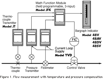 The
absolute temperature is a theoretical temperature, the minimum point (0 K) of
which corresponds to -273.2°C. The following equation is used for the conversion
of °C into K: The
absolute temperature is a theoretical temperature, the minimum point (0 K) of
which corresponds to -273.2°C. The following equation is used for the conversion
of °C into K:The absolute pressure is a theoretical pressure, the minimum point (0 kg/cm2 ABS) of which corresponds to vacuum. However, in process instrumentation, the gauge pressure is usually used, the zero point (0 kg/cm2 G) of which corresponds to the atmospheric pressure. The following equation is used for the conversion of the gauge pressure into the absolute pressure: |
 Figure
1 shows an example where temperature and pressure dependent flow variation is
compensated by using the gas temperature measured via a thermocouple and the gas
pressure measured via a pressure transmitter. The field programmable thermocouple
transmitter, Model JT, is used to obtain a linear temperature signal of 1 –
5 V DC, and the current loop supply, Model YVD, is used for an isolated output
from the pressure transmitter. Figure
1 shows an example where temperature and pressure dependent flow variation is
compensated by using the gas temperature measured via a thermocouple and the gas
pressure measured via a pressure transmitter. The field programmable thermocouple
transmitter, Model JT, is used to obtain a linear temperature signal of 1 –
5 V DC, and the current loop supply, Model YVD, is used for an isolated output
from the pressure transmitter.The temperature and pressure compensated flow signal is displayed on a bargraph indicator and also used to operate a control valve. The math function module does not have an indicator, therefore an engineering unit scale is not used for the multiplication-division, just like the addition-subtraction. Its input and output signals are limited to 4 – 20 mA DC or 1 – 5 V DC. Computations within the module are performed by using numerical values from 0 – 1 or 0 – 100%. For multiplication-division, an individual base point is set for temperature and pressure. These base points are referred to as base temperature and base pressure. If the gas is in the same condition as the base temperature and base pressure, no compensation is required. Then, the input flow signal can be used as an output. |
Gain Calculation (Pressure Compensation) |
|||||||
 First,
let us consider pressure compensation. The gain was fixed for the adder-subtractor
module. But, for the multiplier-divider, the gain varies with pressure. The pressure
dependent compensation equation is shown below: First,
let us consider pressure compensation. The gain was fixed for the adder-subtractor
module. But, for the multiplier-divider, the gain varies with pressure. The pressure
dependent compensation equation is shown below:Where,
The range of gain variation that corresponds to pressure changes from 0 – 100% can be calculated with this equation. In this calculation, the measuring range scale of the pressure transmitter should be converted to absolute pressure from the gauge pressure that is usually used. The numerator, 1.033, is the converted absolute value corresponding to the gauge pressure of 0 kg/cm2 G. If the minimum pressure (0%) of the pressure transmitter measuring range is 2 kg/cm2 G instead of 0 kg/cm2 G, then the numerator should be 3.033 (kg/cm2 ABS). In this case, the gain K1 should be also modified because of the resultant measuring span change of the pressure transmitter. K1 and K2 can be calculated by using the procedure explained above. A practical calculation example is shown below:
Then, the pressure compensation equation becomes: |
Gain Calculation (Temperature Compensation) |
|||||
| Next, let us consider temperature compensation. The temperature
dependent compensation equation is shown below: Where,
The following equation is used to calculate the gain K3: The minimum pressure (0% value) is usually 0 kg/cm2, but the minimum temperature (0% value) is not always 0°C. Therefore, the minimum (0%) temperature value is used to calculate the bias K4 as follows: A practical calculation example is shown below: Then, the temperature compensation equation becomes: |
Gain calculation (Temperature and pressure compensation) |
||||||||
| Simultaneous temperature and pressure compensation is obtained
by multiplying both the temperature and pressure compensation equations. Where,
|
Gain and Bias Check |
| In this chapter, gains and biases that were calculated in the previous chapters will be checked. With base pressure and base temperature, the math function module flow output should be the same as its flow input. In other words, either value of pressure and temperature compensation coefficients should be unity. This is confirmed below: |
| PRESSURE COMPENSATION The value in the parenthesis is the compensation coefficient. Then the base pressure value 0.6 [ = 6 kg/cm2 ÷ (10 – 0) kg/cm2 ] is substituted for X2 in it. The compensation coefficient distinctly shows unity. The small error is from the rounding of numbers in gain and bias calculations. |
| TEMPERATURE COMPENSATION The value in the parenthesis is the compensation coefficient. Then the base temperature value 0.6 [= 300°C ÷ (500 – 0°C)] is substituted for X3 in it. The temperature compensation coefficient also shows unity with the base temperature. |
Differential Pressure Type Flow Measurement with an Orifice Plate |
| In this case, flow is obtained by extracting the square root
of the differential pressure. Then, the pressure and temperature compensation
equation becomes: |
Gain and bias calculation was explained in this article based on a premise that the measured gas is an ideal gas. Common gases used in manufacturing plants are not ideal gas in its exact meaning. However, the calculation procedure explained above is generally used as long as its error is within an allowable range. If an unacceptable discrepancy appears, the calculation result should be corrected by multiplying it by some factor. When steam flow is pressure compensated, a standard math function module cannot always reach the precise compensation. Besides, temperature compensation for petroleum flow measurements according to ASTM standards is impossible with a multiplier-divider module. In this case, a temperature-density relation table stored in computer memory is used for the compensation. Even for a DCS, this cannot be dealt with in a field controller. A separate computer is frequently used for this purpose. Also in the case of steam flow measurements, a steam pressure-density relation table stored in computer memory is used for its wide range and precise compensation due to its non-linear relationship. Within math function modules, especially when they are used as a multiplier-divider, sometimes gain values become very large and cause occasional data saturation problems. This results in inaccurate output signals and disturbances in plant operations. As for M-System’s math function modules, Models JFK and JF, internal data can be handled without saturation up to a limit of 50,000%. Therefore, they can be used easily without concern for inner data saturation problems. |