1/8 DIN size New Digital Panel Meters, LCD Display Type |
|||||||||||||||||||||||||||||||||||||||||||||||||||||||||
The easy-to-use 47 series retains our noted performance and functionality in a new stylish design.
LCD display type models augment the above features with an additional range of functionality. |
|||||||||||||||||||||||||||||||||||||||||||||||||||||||||
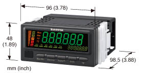
1. Display
Figure 1 Illustrates the external appearance of 47 Series LCD display type models, while Figure 2 provides a diagram of the front panel. |
|||||||||||||||||||||||||||||||||||||||||||||||||||||||||
2. Operability
The 47D models are designed to fulfill the seemingly contradictory demands of intuitive operation and extensive functionality. The goal of the design process was to allow users to understand basic operations and use after reading through the instruction manual one time. The features most frequently used initially after powering on the meter are likely to be the alarm setting function and the scaling function. Each of these functions have been assigned to a single button located on the front panel and labeled with the name of the function to allow instant access to setting mode. There is also a security function to prevent unintended setting changes. Models take advantage of the detailed display made possible by the use of an (11) Shift buttonLCD as described above to offer the maximum possible level of functionality while delivering intuitive operation. Table 2 lists a selection of representative functions. |
|||||||||||||||||||||||||||||||||||||||||||||||||||||||||
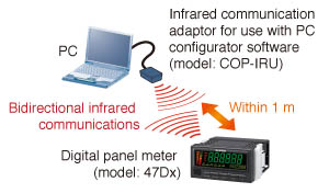
3. Infrared Communications
LCD display type 47 Series models support an infrared communication adaptor (model: COP-IRU). The adaptor can be used to configure the device from a computer without requiring either a cable connection or access to the unit’s front panel (see Figure 3). PC configurator software (model: 47DCFG) is also available for use with the adaptor. The software can be downloaded from our website. Used in combination with the PC configurator software, this infrared communication adaptor eliminates the need to check various settings while repeatedly pressing the buttons on the unit’s front panel. Instead, you can set and check settings on a large computer screen. Additionally, the ability to edit, save, and load equipment parameters and manage parameter files eliminates the fuss when using control panels equipped with multiple 47 Series digital panel meters as long as the meters use the same settings. You need only load the parameter file and write (send) it to each unit. |
|||||||||||||||||||||||||||||||||||||||||||||||||||||||||
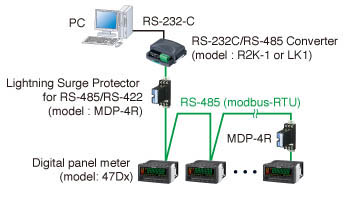
4. DC Output and Modbus Communications
DC output has five calibration types available (4 to 20 mA, 0 to 20 mA, 0 to 5 V, ±5 V, and ±10 V) using the buttons on the unit’s front panel to configure without changing terminal block connections. The withstand voltage between inputs and DC outputs is AC 2,000 V for 1 minute. Furthermore, the 47 Series meters offer a loop test function for which output can be set to the desired value, a convenient feature when getting a system up and running. 47 Series also offer RS-485 Modbus communications, allowing them to send measured values or setting values to an upstream computer or other device making it easy to implement data gathering and analysis from multiple meters. Additionally, the full range of meter functionality is supported, including the changing of alarm values and display colors. Figure 4 illustrates an example system architecture. |
|||||||||||||||||||||||||||||||||||||||||||||||||||||||||
5. Excitation Supply The 47 Series includes an excitation supply. Users can choose from two-wire transmitter excitation (+24 V) and sensor excitation (+12 V) at the time of purchase (except for 47DAC). With two-wire transmitter excitation models, you can monitor and display 20 mA transmitter output just by connecting a DC input type meter (47DV) to a two-wire transmitter with two wires. Smart transmitters (e.g., with HART) are also supported. Additionally, units with either type of excitation supply now display an error on the front panel when an unexpected shortcircuit occurs. Naturally, a shortcircuit protection function is included. |
|||||||||||||||||||||||||||||||||||||||||||||||||||||||||