| DC/Potentiometer Converterr — CVR1 |
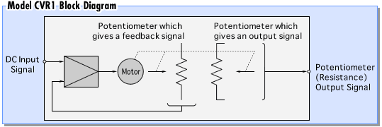
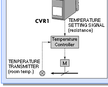
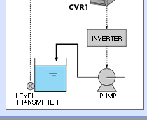
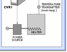
| Model CVR1 is a signal
conditioner that converts an analog DC signal to a resistance output signal by
setting a potentiometer slidewire contact position automatically. This is used
most effectively when upgrading a manually adjusted valve or motor speed device
to an automatic system. • Wide Selection of Output Resistances The following resistance values are available as standard outputs: 100, 135, 200, 500, 1K, 2K, 5K, 10K, 20K, 50K and 100K ohms (Power dissipation is limited to 1 Watt or less). • Compact, Standard Housing, No Moving Parts All components including any moving parts are enclosed in the standard M-Unit style housing. Plug-in socket construction allows for easy installation and trouble shooting. Wall or DIN rail mounting is standard. |
|||||||||||||||||||||
 |
|||||||||||||||||||||
| The CVR1 is designed to keep sufficient
durability in spite of using a potentiometer which has a sliding contact mechanism
by using the following several developments: AUTOMATIC DEADBAND ADJUSTING CIRCUIT Often there are cyclic variations (hunting) in a control output signal from a PID controller. The detectable frequency of this phenomenon depends largely on the input signal variation and the PID parameter values. Variations in control signals occur very often especially when an auto-tuning type PID controller is used. If a pneumatic actuator is used or if solid-state motor speed control circuits are used, the above mentioned cyclic variation in the control output signal has no effect on the instrument’s durability. However, when a potentiometer is driven by the controller output signal, the cyclic variation affects its durability due to the potentiometer’s mechanical characteristics. A newly designed automatic deadband adjusting circuit widens the deadband automatically when the cyclic variation in the control signal increases. The circuit also causes the deadband to narrow automatically and gradually when the cyclic variation decreases. By implementing this new circuit, satisfactory potentiometer durability is obtained even when the deadband is set to a minimum of 0.2% of full span. MOTOR START LIMITING TIMER
A filter is usually used in order to remove any ripple noise. However, this method also makes the overall signal response very slow when the low frequency component should be removed. In the model CVR1, a filter is used for removal of the high frequency noise component, and a motor start limiting timer is used as a method to remove the low frequency components. By limiting the time between motor re-start after it has stopped, frequent repetitions of starting and stopping can be avoided. In this case, when a motor is first started, it continues to turn until it becomes “balanced”. As a result, the response time receives minimal bad effects from the limiting timer. By utilizing this limiting timer circuit, potentiometer durability was significantly improved. MOTOR LOAD DERATING Motor life is typically defined as the usable time while operating at the rated load and rated rotation speed. That is to say, motor life is lengthened by lightening its load and lowering its rotation speed. Concerning the Model CVR1, the largest size (highest power) motor was selected that could be enclosed within the standard M-Unit style housing. In addition, the motor driving voltage was chosen significantly lower than its rated value. At the same time, the potentiometer driving mechanism was improved to decrease its frictional resistance so that the potentiometer could be operated normally in the above mentioned derating conditions. |
|||||||||||||||||||||
 |
 |
 |
 |
 |
 |